Image resolution in 3d world
At the moment, the biggest issue in cartilage imaging is spatial resolution. It is not just a question of if there is cartilage on joint facets or not, but cartilage also has certain layers that should be identified in optimal imaging. Data gathering in magnetic resonance imaging requires time. Increasing imaging time improves image quality, but in clinical work imaging time of a single sequence is limited to just couple of minutes. This gives an image data with 1 to 1,5 mm actual resolution with about 3 mm slice thickness. Final resolution of images can be higher, but that is then mathematical extrapolation and gives an artificial improvement in image resolution. It does not increase real resolution.
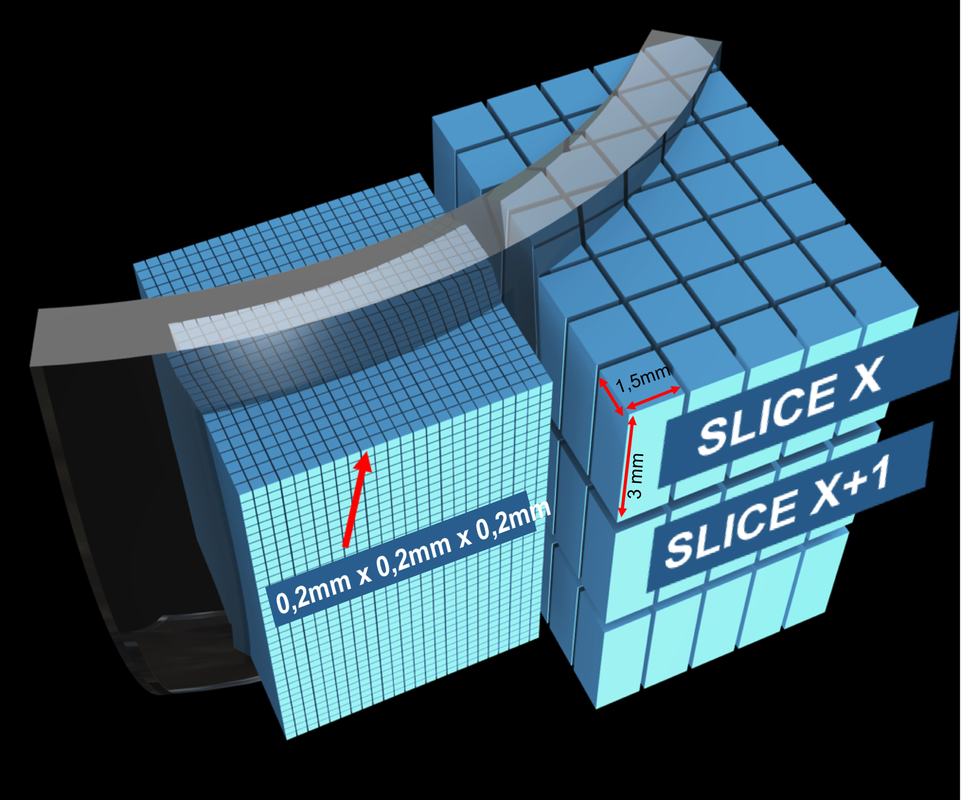
Original isotropic cone beam CT data is based on symmetrical 0.2mm x 0.2mm x 0.2mm voxels. In this imaging method, original data has very high resolution, and the final pixels for image reading are formed by grouping and calculating a desired slice thickness which can be anything from 0.2 mm to whole image area. Clinical experience indicates that 0.8 mm slices with 0.4 mm step is enough to show all clinically relevant cartilage issues. Mathematically CBCT resolution can be even 300 times higher than in routine clinical MRI. In addition, isotropic data means, that cartilage lesion evaluation and decision making is not limited to a fixed slice orientation decided during original imaging.
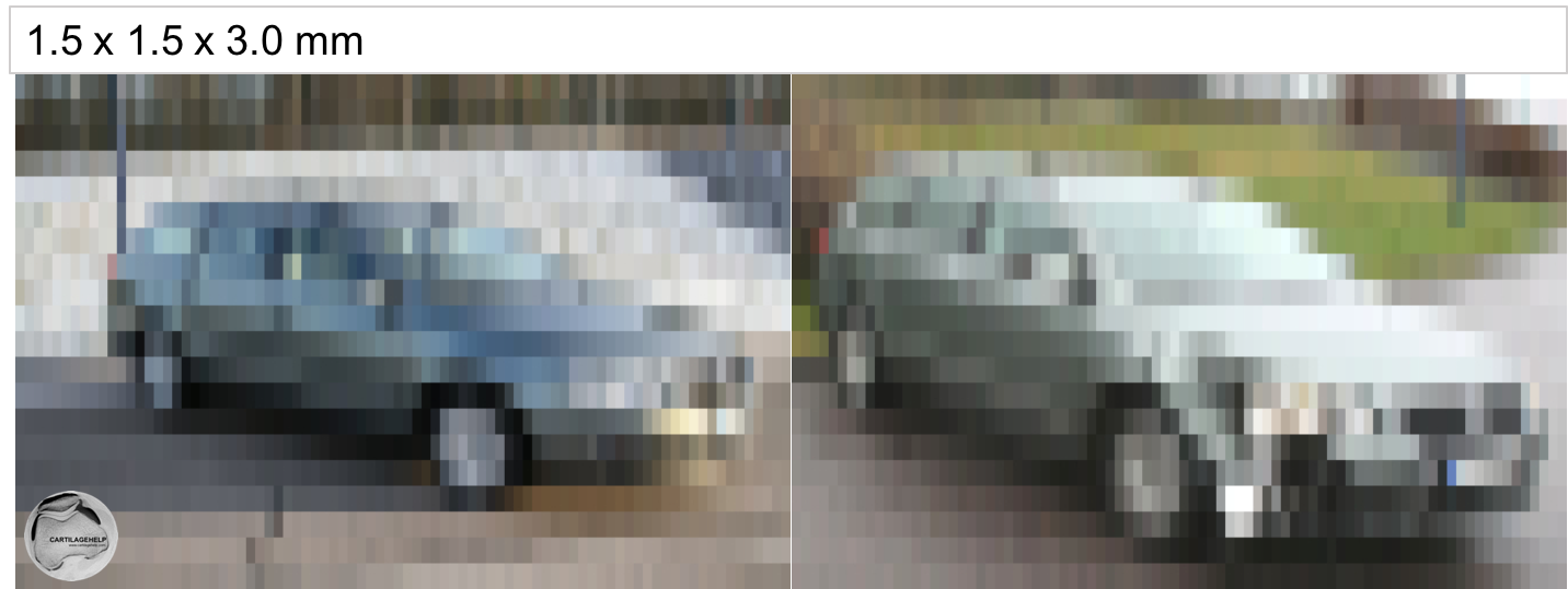
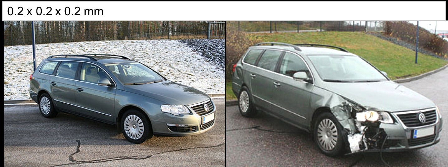
Pictures below demonstrate the difference of image quality with different pixel size. Left picture represents routine MRI image resolution. The size of 3D pixel in routine MRI is 1,5mm x 1,5mm x 3mm. Right picture represents CBCT image resolution, where 3D pixel is symmetric in all three directions and it's size is 0,2mm x 0,2mm x 0,2mm. Real clinical examples can be seen on this site.
Original isotropic cone beam CT data is based on symmetrical 0.2mm x 0.2mm x 0.2mm voxels. In this imaging method, original data has very high resolution, and the final pixels for image reading are formed by grouping and calculating a desired slice thickness which can be anything from 0.2 mm to whole image area. Clinical experience indicates that 0.8 mm slices with 0.4 mm step is enough to show all clinically relevant cartilage issues. Mathematically CBCT resolution can be even 300 times higher than in routine clinical MRI. In addition, isotropic data means, that cartilage lesion evaluation and decision making is not limited to a fixed slice orientation decided during original imaging.
Pictures below demonstrate the difference of image quality with different pixel size. Left picture represents routine MRI image resolution. The size of 3D pixel in routine MRI is 1,5mm x 1,5mm x 3mm. Right picture represents CBCT image resolution, where 3D pixel is symmetric in all three directions and it's size is 0,2mm x 0,2mm x 0,2mm. Real clinical examples can be seen on this site.
|
|
Below is a schematic presentation of symmetrical CBCT voxel and MRI voxel. The importance of smaller and symmetrical voxels can be visualized especially in convex and concave joint areas.
MRI images can show soft tissues much better than X-ray based imaging techniques. This makes MRI images to look like highly detailed anatomic pictures, with a lot of details. But keeping in mind the above mentioned resolution issue, cartilage imaging is becomes challenging. One way to demonstrate real resolution in third direction is the following slide show with original slice series intended to be viewed as coronal slices. Yellow side of the cube indicates the direction of view to this data. In sagital and axial view slice thickness 3 mm is clearly visible.
Spatial resolution of CBCT images is equal in all XYZ-directions due to symmetric voxels. In the following example absolute thickness of cartilage in femur and tibia is only 1-2mm, but it is still visualized in all planes. Yellow side of the cube shows direction from which the joint is seen.
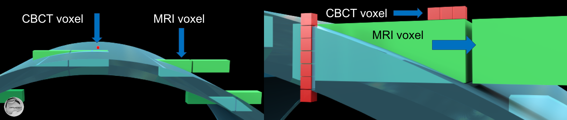
Symmetry and extremely small size of the voxel is of great importance on convex and concave surfaces. Fitting of CBCT and MRI voxel in convex surface is schematically presented in the picture below.
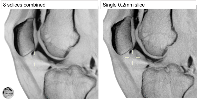
Slice thickness in CBCT
CBCT data originally gives a 0.2 mm thin slice seen in the right hand side image. It looks coarse, and is not the best image reading. For human eye, any slice thickness can be recalculated, on the left hand side an example of 1,6 mm slice thickness giving a smoother appearance.
perpendicular view of curved structures
As the CBCT data is stored as the cloud of symmetrical voxels, it is possible to see cross-section of the joint structures in any direction. Thus, it is possible to measure cartilage thickness always in perpendicular plane to joint surface. Examples below show cross-sectional measurements of thick cartilage in femoral medial condyle (34 years old male, right knee). Three last images are delayed images of a different knee, showing remarkable contrast media penetration inside cartilage. This makes images more blurry, difference to arthrographic phase imaging is remarkable. In many areas, contrast media is in direct contact with bone.
free viewing angle
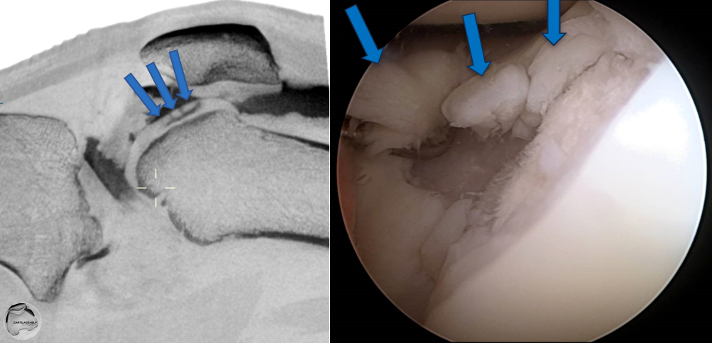
Joint can be observed from any angle without compromising the image quality. Images below show how cartilage lesion in trochlea can be visualized with CBCT multiplanar reconstruction. On the right side of each image red lines demonstrate the axis of image in axial, coronal and sagittal planes.
The same cartilage lesion is presented in sagittal plane (image rotated) and how it actually looks in arthroscopy.
|
|
The content of this website is provided for information only and is not intended to be used for diagnosis or treatment or as a substitute for consultation with your own doctor or a specialist.Email addresses supplied are provided for basic enquiries and should not be used for urgent or emergency requests, treatment of any knee injuries or conditions or to transmit confidential or medical information.
|